Arduino USB Connection
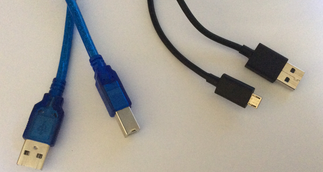
The first step is to get a USB cable that is the same size as the connector port on your board. For example, the Arduino Uno needs a Type-B USB data cable whereas the Arduino Due requires a Micro-B USB cable. The Due has two USB ports (Native USB and Programming) so plug your USB cable into either one of the two ports.
Connect the other end of the USB cable to your computer's USB port and make sure the green LED on your Arduino board is blinking. Always check for any damages to the board before using it in case you have received a damaged board. If you don't have the right cable, you can power your board by an external power supply using a battery box with 6 AA batteries or 9 volts but you will be unable to program it via computer.
To spot fake/counterfeit boards, click here.
Arduino IDE (Integrated Development Environment)
To upload and write code to the Arduino, you need to download the Arduino IDE, compatible software specially created to program Arduinos. The IDE can compile, upload & save the code to your sketchbook and can be downloaded onto almost any operating system including Windows, Mac and Linux.
The official Arduino website is where the latest releases & versions to the IDE are and therefore, the IDE can be downloaded from there as well. Please click here to be redirected to the Arduino website. In this example, the Arduino IDE will be downloaded to the Windows operating system. Downloads to other operating systems may vary in instructions.
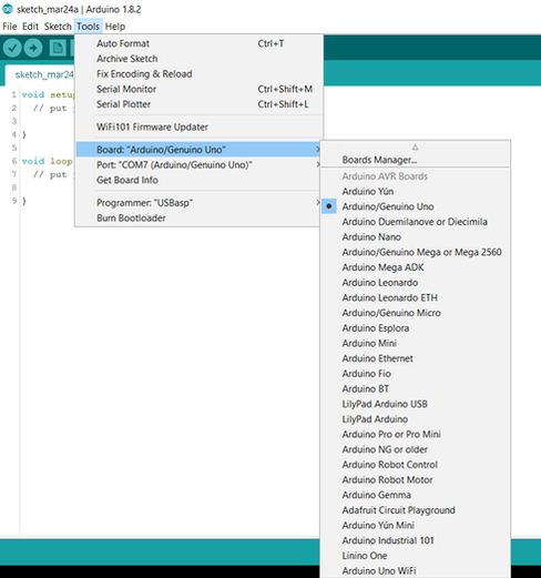
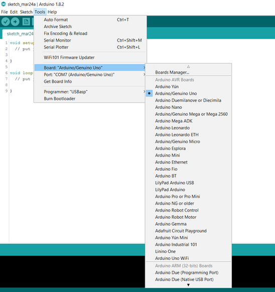
After you have downloaded, extracted and opened the IDE, plug in your Arduino board. Go to Tools > Board and select your Arduino board. Then, go to Tools > Serial Port and choose the USB port your board is plugged into. For other boards, you will have to download their respective drivers.
Setting up the drivers
The downloading of drivers is fairly easy but if the IDE does not recognise the board you are using, follow this procedure. This problem is common when using clone Arduinos with a different on-board driver chip (CH340) and when you plug in the board to your computer, it immediately disconnects. Normally, Windows Installer will download drivers automatically upon plugging the board in but if your computer does not identify the board, downloading drivers is essential. Start by plugging in your board to get started:
- First, open up Control Panel.
- Then click on System & Security and then on System.
- Once in System, go to Device Manager and click on Ports (COM & LGT).
- Under Ports, right click on Arduino Uno and select Update Driver Software. By clicking on that, it will take you through a process to download the appropriate driver(s) automatically.
- During that setup process, click "No, not this time" for one of the pages.
- On one of the other pages, you will receive an option to "Install from a list or specific location", click that.
- When you get to a page asking to select a specific file, browse your files and choose the one where all your hardware is located by selecting two options from that page: "Search for the best driver in this location" and "Include this location in the search". Otherwise, select the file and continue.
- The next page will inform you of the installation so just wait for a moment and it will finish.
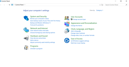
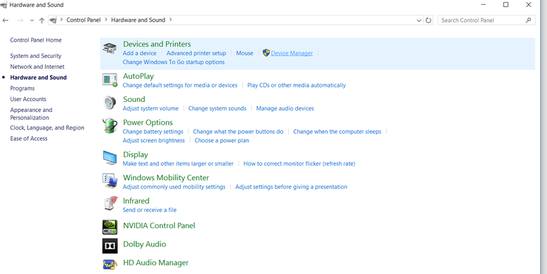
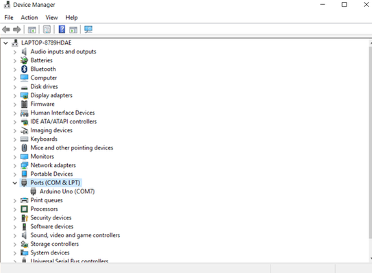
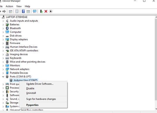
The drivers are now downloaded and if you go to the IDE, it should identify the board correctly. By clicking here , you will be able to review over the steps again but with pictures.
The drivers for boards such as the Arduino Duemilanove, Diecimila, Leonardo, Micro, Uno and others are already installed within the IDE automatically but drivers for other offcial & recognized Arduino boards (Arduino Due for example) will need to be downloaded manually and this can be done directly from the IDE.
- First, go to Tools > Boards > Boards Manager.
- You will see a window listing all the recognized different boards so just search for your correct board.
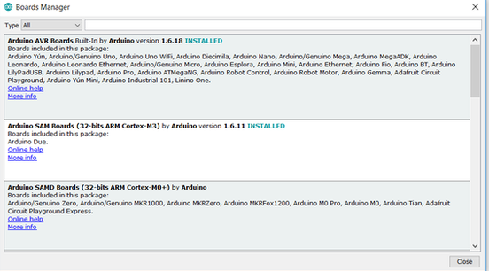
- Once you find the right board, click Install.
- After installing, close the Boards Manager window and restart the Arduino IDE.
- Once the IDE is opened up again, go to Tools > Boards and your board should be listed there.
Testing the board
Once you have completed the above, you will have to test the board.
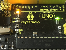
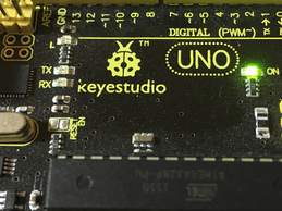
- Plug your Arduino board (a Keyestudio Uno is used within the images) into your computer and open the Arduino IDE.
- Go to File > Examples > 01. Basics > Blink. By clicking Blink, a new example sketch will open.
- Upload the sketch to the board. After uploading, the on-board LED should turn on for a second, then turn off for a second repeatedly.
- If you press the reset button on the board, the LED will blink rapidly to then start the process again.
Explaining the code
After overseeing the circuit, the code will now be explained.
Comments on sketches usually start with // or /* but it is not part of the code and is ignored by the IDE.
The first line of code is void setup as Arduino skethces must have two compulsory commands; void setup and void loop. The void setup is the part which only runs one time before void loop, which runs repetitively.
In this particular sketch, void setup declares that the pin 13 LED is going to send data out (OUTPUT), to control the LED.
The second part of this code is under void loop since the LED blinks infinitely, making a loop. First, pin 13 is set HIGH (which turns the LED on). DigitalWrite is simply a function declaring what to do with the LED (turn on or turn off), which we then code to output the results we want.
The next line of void loop is a delay command, which is similar to a pause as it stops the circuit. The length of the delay is set to a second (1000 ms). Milliseconds is the unit of time used when working with delays.
In the next line, pin 13 is set LOW (turns off the LED).
Finally, the code is complete. The loop section will repeat until power is removed to the Arduino board.